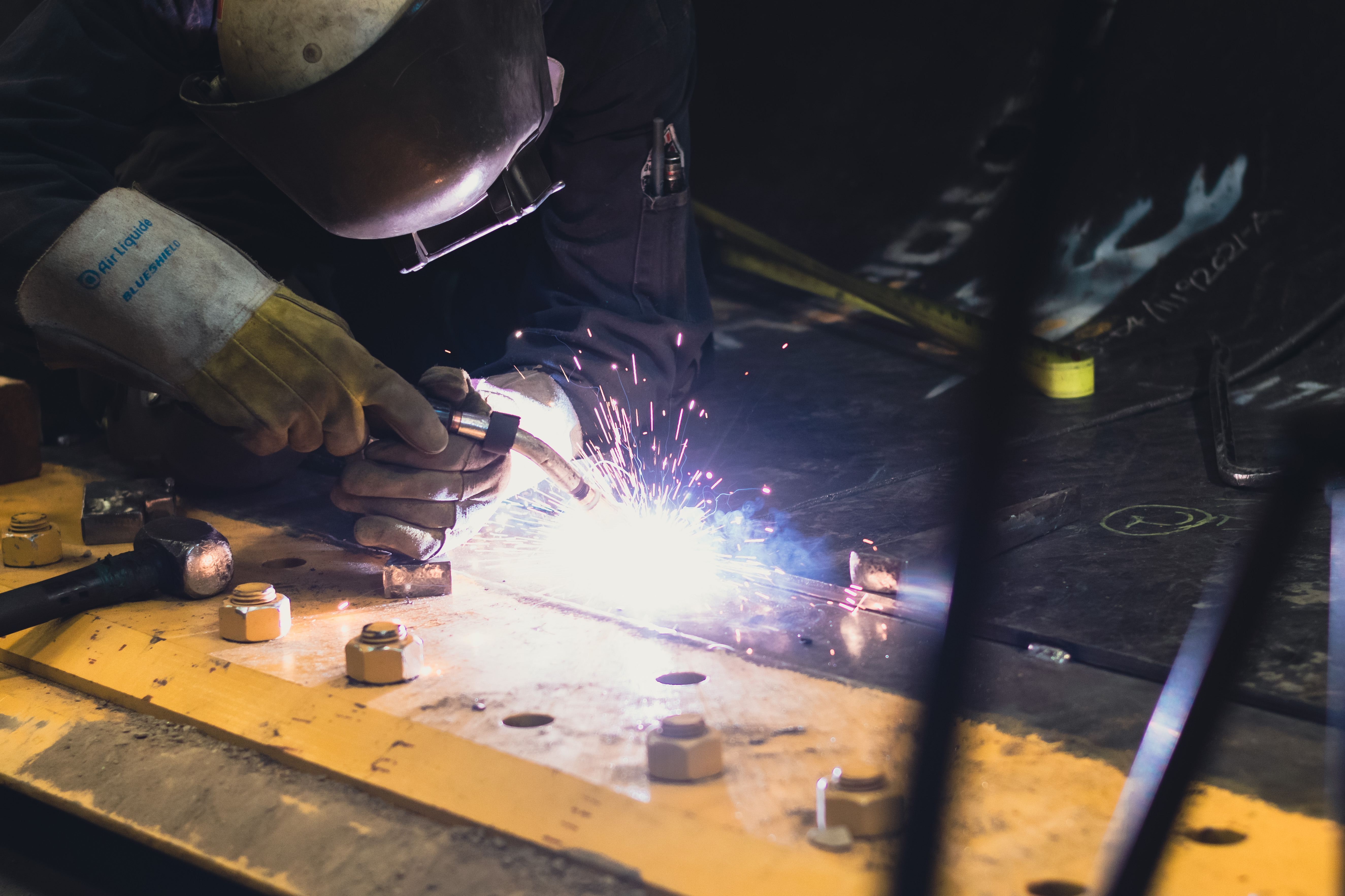
PREPARATION
Ensure that all weld zones are clean and free of paint, rust, grease, and other contaminants.
ATTACHMENT METHOD
Raptorplate® is most commonly attached by weldments placed around the plate’s perimeter and in the plug/slot locations. Raptorplate® can also be attached mechanically with bolt-on plates that have studs welded onto the mild steel side of the plate. Contact your Raptor sales representative for more information about mechanical attachment and other attachment means.
PREHEATING
The mild steel side of Raptorplate® is A36 material and has a preheat requirement of 32 degrees Fahrenheit/ 0 degrees Celcius. A light “sweat” with preheating torches is what we recommend when working in cold weather climates. Regardless of any specific Raptorplate® preheat requirements, you must follow the parent material’s preheating, inter & post heat requirements. Failure to do so may result in weld cracking or damage to the parent material.
FITMENT
The only thing that limits the weld position is the choice of the welding process. If the liner plates do not make complete contact with the parent material, the gap between the plates can cause cracking while in service. Ensuring no gap is essential in applications that see impact wear like dump bodies and hoppers.
1) Tack the wear plate in place and ensure Raptorplate® is fit with minimal gap
2) For SMAW, we recommend a minimum 200A power supply. For GMAW, we recommend a minimum 250A 100% duty cycle constant voltage power supply.
3) Maintain roughly a 1/8” gap between the weld pool and Chrome Carbide. Do not allow the weld pool to contact the chrome carbide hard facing, resulting in carbon pickup from the alloy and consequent weld cracking.
4) Place a full perimeter fillet weld around the entire plate. Any plugs and slot welds should be completed before the perimeter welding.
5) An optional pass of chrome carbide overlay can be placed over the attachment welds. Care must be taken to ensure any welded overlay does not contact the parent material.
WELDING
Parameters:
1) Electrode: 70 Series filler metals or greater preferred, or as required by base metal
2) Processes: GMAW, FCAW, SMAW
3) Weld Size: Dependant on plate thickness
4/5 mm – 3 mm fillet weld
6/6 mm – 4 mm fillet weld
10/8 mm – 5 mm fillet weld